
Ottima segnalazione max. Grazie.
Ho dato un occhiata veloce allo script, ma non ho capito come avviene l'inseguimento.
Non ho visto coordinate del sito da inserire, hai idea di come funziona?
Piranometro Arduino, qualcuno l'ha installato?

Re: Piranometro Arduino, qualcuno l'ha installato?
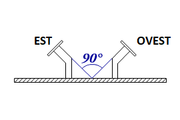
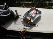
Il principio di funzionamento è molto semplice: si posiziona la scatola con le due fotoresistenze ed il servomotore verso SUD; le due fotoresistenze, poste a 90° l’una rispetto all’altra, così come in figura, fanno in modo che quando il sole è verticale sull'asse Y (ore 12), esse abbiano un valore di resistenza identico. Al muoversi della terra rispetto al sole, da Est ad OVEST, una delle due rileverà più luce dell’altra e incrementerà la propria resistenza sbilanciando il circuito e facendo rilevare ad arduino una variazione rispetto al punto iniziale. In questo modo Arduino inizierà a seguire il sole ossia a spostare il servo e con esso il sensore BH1750, per ribilanciare il valore letto dalle due fotoresistenze. Il sensore BH1750 rileverà l'irradiazione solare restituendo un valore in lux,che si potrà leggere o direttamente con il monitor seriali di arduino, oppure tramite PLX-DAQ-v2.11.
Il sistema è ancora in fase di sperimentazione e va sicuramente migliorato. Ho rilevato, infatti, che ogni tanto arduino restituisce degli errori di lettura dalla porta COM(7), ma non riesco a capire il problema. probabilmente c'è un errore nello sketch.
Il sistema è ancora in fase di sperimentazione e va sicuramente migliorato. Ho rilevato, infatti, che ogni tanto arduino restituisce degli errori di lettura dalla porta COM(7), ma non riesco a capire il problema. probabilmente c'è un errore nello sketch.
Re: Piranometro Arduino, qualcuno l'ha installato?
Salve a tutti.
Riattivo questa discussione perchè vorrei importare i valori di illuminamento solare rilevati con il sensore BH1750 in metern, tramite il file python seguente:
- prendo i dai da arduino, dove è caricato uno sketch apposito (scritto da altri);
- creo il file metern7;
- imposto il sensore BH1750 come misuratore (sensor);
- modifico il file reqsdm.php nel modo seguente:
- ottengo un errore nella dashboard;
- apro il file metern7.txt e mi accorgo che c'è un errore di scrittura del valore, confrontandolo con il file metern1.txt relativo ad un contatore sdm120:

- corrego manualmente il file metern7.txt e magicamente...
il valore dell'illuminamento solare appare in dashboard correttamente. Naturalmente, prima ho fermato il file python di cui sopra.
Ora chiede se qualcuno, gentilmente, mi può dare un aiuto/consiglio per sistemare la cosa.
Dopo numerosi tentativi, inutili, e qualche giorno di impazzimento totale mi sono arreso... Non so più dove sbattere la testa, già di per se compromessa . Grazie e buona vita a tutti.
Riattivo questa discussione perchè vorrei importare i valori di illuminamento solare rilevati con il sensore BH1750 in metern, tramite il file python seguente:
- prendo i dai da arduino, dove è caricato uno sketch apposito (scritto da altri);
- creo il file metern7;
- imposto il sensore BH1750 come misuratore (sensor);
- modifico il file reqsdm.php nel modo seguente:
- ottengo un errore nella dashboard;
- apro il file metern7.txt e mi accorgo che c'è un errore di scrittura del valore, confrontandolo con il file metern1.txt relativo ad un contatore sdm120:
- corrego manualmente il file metern7.txt e magicamente...
il valore dell'illuminamento solare appare in dashboard correttamente. Naturalmente, prima ho fermato il file python di cui sopra.
Ora chiede se qualcuno, gentilmente, mi può dare un aiuto/consiglio per sistemare la cosa.
Dopo numerosi tentativi, inutili, e qualche giorno di impazzimento totale mi sono arreso... Non so più dove sbattere la testa, già di per se compromessa
Re: Piranometro Arduino, qualcuno l'ha installato?
Anche questa volta mi rispondo da solo.
Non è stato facile per me arrivare al risultato, nonostante l'aiuto di altri utenti, ma alla fine sono riuscito ad importare i dati di arduino (sensore luce BH1750) in metern
Non è stato facile per me arrivare al risultato, nonostante l'aiuto di altri utenti, ma alla fine sono riuscito ad importare i dati di arduino (sensore luce BH1750) in metern
Re: Piranometro Arduino, qualcuno l'ha installato?
maxsemp ha scritto:Anche questa volta mi rispondo da solo.
Non è stato facile per me arrivare al risultato, nonostante l'aiuto di altri utenti, ma alla fine sono riuscito ad importare i dati di arduino (sensore luce BH1750) in metern
Prima di leggere questa discussione non sapevo nemmeno cosa fosse un sensore BH1750. Posso chiederti più info a riguardo? Hai seguito qualche guida? Hai per caso scritto degli appunti che puoi condividere? (per esempio "prendo i dai da arduino, dove è caricato uno sketch apposito (scritto da altri)" riesci a condividere lo sketch o la fonte? )
Diciamo che visto che ci hai lavorato tanto (e non è stato facile per te, figuriamoci per me!) non mi cemento se non sono certo di riuscire a portare a termine il progetto =)
Grazie in anticipo per la risposta
Re: Piranometro Arduino, qualcuno l'ha installato?
Ciao metus.
Scusa il ritarrdo; non avevo visto il tuo post.
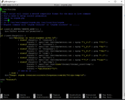
lo scketch che uso su arduino uno è il seguente:
Tengo a precisare che lo scketch non lo scritto io; lo ho solo copiato ed adattato alle mie esigenze e funziona perfettamente ancora oggi.
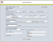
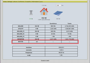
Il BH1750 è configurato come sensore in metern.
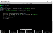
Il file python che uso è il seguente:
... e questo è il risultato...

Scusa il ritarrdo; non avevo visto il tuo post.
lo scketch che uso su arduino uno è il seguente:
Codice: Seleziona tutto
// BH1750.ino
// ----------
// 17 august 2016
//     First version by Koepel. Public Domain.
//     Tested with Arduino Uno and Arduino.cc IDE 1.6.9
//     In 2016, there are about 10 to 20 libraries for the BH1750,
//     but I was not happy with the existing code.
//     I started from scratch and tried to get the maximum out of the sensor.
//
//
//
//
// Light sensor BH1750FVI info
// ---------------------------
// Manufacturer : Rohm Semiconductor, Japan.
// Normal range : 1 lux to 65535 lux
// Extended range : 0.11 lux to 100k lux (by adjusting the measurement time)
// There is a Japanese and English datasheet.
// The newest datasheet is "2011.11 - Rev.D" for both languages.
//
// The power usage in power down mode is typical 0.01 uA, and maximum 1.0 uA.
// That current is measured with no light.
// The 1.0 uA is hundred times more than 0.01 uA.
// It it not known why it is such a big difference, or why it was measured with no light.
//
//
// Sensor in the dark
// ------------------
// The sensor is not very accurate with 20% measurement variation.
// The best resolution is 0.11 lux.
// That means that light below 0.11 lux can not be measured.
// One lux is the light from a candle at 1 meter distance.
// Moonlight is about 0.5 lux.
// A LDR with a high resistor value (200k) and with averaging in software is able to detect below 1 lux.
// The maximum time to collect light for the BH1750 is about 441 ms.
// It is not possible to lengthen that time.
// Sensitive photo diodes can measure 1 mlx (0.001 lux).
//
//
// Sensor in bright light
// ----------------------
// The sensor should perhaps be able to (almost) measure direct sunlight with the 100k lux range,
// but the sensor is not ment to be used in direct sunlight.
// The best way to measure bright light, is by placing the sensor under semi-transparant material.
// The maximum temperature is 85 degrees Celsius.
//
//
// BH1750 Software interface
// -------------------------
// It is a chip for 3.0 or 3.3V and uses I2C up to 400kHz.
// The BH1750FVI can receive one byte, and two bytes can be read from it.
// It does not support a repeated start.
// The one byte that is send can be a command or a few data bits for the measurement time register.
// The two bytes that are received is the light intensity.
//
// It might be possible to have many BH1750s connected to the I2C bus and select just
// one by changing the I2C address with the ADDR pin of that one sensor. Not tested yet.
//
// Only 3 commands of the possible 16 (the lower nibble) are used.
// It is not known if there are other undocumented commands.
//
//
// Measurement and test results
// ----------------------------
// 1 )
// It is not possible to detect light below 0.11 lux.
// There is no noise that can be averaged to get below it.
//
// 2 )
// There is sometimes a difference between the normal high resolution
// and the high resolution mode2. Sometimes 0.5 lux.
// When automatically changing between the two, perhaps changing at a higher
// lux is better, for example at 50 or 100 lux and not at 10 lux.
//
// 3 )
// With the high resulotion and minimal time measurement period, the
// lux can go up to 120k lux in direct sunlight.
// (The sensor is for ambient light, not for direct sunlight)
//
// 4 )
// There is no status bit or interrupt to indicate that the sensor has finished measuring.
// During the measurement time, the sensor does acknowledge to its I2C address in a normal way,
// and does return the value of the illuminance data register. That is however,
// the data of the previous measurement.
// When the measurement time has finished, the new value will be written
// in the illuminace data register.
// A reset command clears the illuminance data register, therefor that can be
// used to determine if a new value is ready, unless it was very dark
// and the light was 0 lux.
//
// 5 )
// Measurement times
//    low resolution  : typical 16 ms, max 24 ms, measured : 18 ms
//    high resolution : typical 120 ms, max 180 ms, measured : 134 ms
//


#include <Wire.h>

// The I2C address is 0x23 (ADDR pin is low) or 0x5C (ADDR pin is high).
#define BH1750_I2C_ADDRESS_1        0x23
#define BH1750_I2C_ADDRESS_2        0x5C

#define BH1750_POWER_DOWN           0x00    // Stop all operations
#define BH1750_POWER_ON             0x01    // Power on and wait for measurement command
#define BH1750_RESET                0x07    // Clears the illuminance data register, does not work in power down.
#define BH1750_CONT_H_RES_MODE      0x10
#define BH1750_CONT_H_RES_MODE2     0x11
#define BH1750_CONT_L_RES_MODE      0x13
#define BH1750_ONE_TIME_H_RES_MODE  0x20
#define BH1750_ONE_TIME_H_RES_MODE2 0x21
#define BH1750_ONE_TIME_L_RES_MODE  0x23
#define BH1750_MEAS_TIME_H          0x40
#define BH1750_MEAS_TIME_L          0x60


// Moving average array.
// A "moving average" is also called "rolling average" or "running average".
#define NUM_SAMPLES_AVG   10
float moving_avg[NUM_SAMPLES_AVG];
int index_avg;


const int _i2c_address = BH1750_I2C_ADDRESS_1;


// The default correction factor to calculate the lux is 1.2.
// Adjust it when you are able to calibrate the BH1750.
// According to the datasheet, the value can be 0.96 to 1.44.
// It is not know if this correction factor is the same for the whole range.
const float BH1750_factor = 1.2;


void setup()
{
  Serial.begin( 9600);
  Serial.println(F( "\nBH1750 lux sensor"));

  Wire.begin();

  // Start the sensor and test if the I2C address is right.
  int error = BH1750_begin();
  if( error != 0)
    Serial.println(F( "Error, BH1750 not found"));

  // Initialize the moving average array.
  for( int i=0; i<NUM_SAMPLES_AVG; i++)
  {
    moving_avg[i] = 0.0;                        // or fill it with the actual current lux value.
  }
  index_avg = 0;
}


void loop()
{
  Serial.println(F( "------------------"));


  // ----------------------------------------
  // Low Resolution
  // ----------------------------------------
  // Low resolution could be a quick check of the light intensity.
  // It could be used to determine which high resolution mode will be used.
  write8( BH1750_POWER_ON);
  write8( mt_H( 69));             // default
  write8( mt_L( 69));             // default
  write8( BH1750_ONE_TIME_L_RES_MODE);
  delay( 24);    // typical 16ms, maximum 24ms
  uint16_t x = read16();
  // Divide the result by a factor of 1.2 (default value)
  // The resulting lux is calculated with float numbers.
  float lux_lowres = (float) x / BH1750_factor;        // BH1750_factor is usually 1.2
  Serial.print(F( "low res   : "));
  Serial.println( lux_lowres);


  // ----------------------------------------
  // High Resolution
  // ----------------------------------------
  // Normal request of the lux in one time high resolution mode.
  write8( BH1750_POWER_ON);
  write8( mt_H( 69));             // default
  write8( mt_L( 69));             // default
  write8( BH1750_ONE_TIME_H_RES_MODE);
  delay( 180);    // typical 120ms, maximum 180ms
  uint16_t a = read16();
  // Divide the result by a factor of 1.2 (default value)
  // The resulting lux is calculated with float numbers.
  float lux = (float) a / BH1750_factor;              // BH1750_factor is usually 1.2
  Serial.print(F( "high res  : "));
  Serial.println( lux);


  // ----------------------------------------
  // High Resolution Mode2 with maximum measurement time
  // ----------------------------------------
  // Extra sensitive 0.11 lux resolution.
  // The MTregister is default 69.
  // It can be minimal 31 and maximum 254
  write8( BH1750_POWER_ON);
  write8( mt_H( 254));          // maximum value of measurement time
  write8( mt_L( 254));
  write8( BH1750_ONE_TIME_H_RES_MODE2);
  delay( 662);           // 180 * 254 / 69
  uint16_t b = read16();
  float lux_dark = (float) b / BH1750_factor * ( 69.0 / 254.0 ) / 2.0;      // BH1750_factor is usually 1.2
  Serial.print(F( "0.11 res  : "));
  Serial.println( lux_dark);


  // ----------------------------------------
  // High resultion with minimum measurement time
  // ----------------------------------------
  // Extra range for bright light up to 100000 lux
  // The calculation could result into a lux value up to 120 klx (120000 lux).
  // Normal High Resolution mode, with minimal time measurement (31 is minimum for MTregister).
  write8( BH1750_POWER_ON);
  write8( mt_H( 31));          // lowest value of measurement time
  write8( mt_L( 31));
  write8( BH1750_ONE_TIME_H_RES_MODE);
  delay( 81);            // 180 * 31 / 69
  uint16_t c = read16();
  float lux_light = (float) c / BH1750_factor * ( 69.0 / 31.0 );       // BH1750_factor is usually 1.2
  Serial.print(F( "100k range: "));
  Serial.println( lux_light);


  // ----------------------------------------
  // moving average
  // ----------------------------------------
  moving_avg[index_avg] = lux_dark;

  // Calculate the average.
  float total_avg = 0.0;
  for( int i=0; i<NUM_SAMPLES_AVG; i++)
  {
    total_avg += moving_avg[i];
  }
  total_avg /= (float) NUM_SAMPLES_AVG;
  Serial.print(F( "average   : "));
  Serial.println( total_avg);

  // advance index for the moving average array.
  index_avg++;
  if( index_avg >= NUM_SAMPLES_AVG)
    index_avg = 0;


  delay( 1000);
}


int BH1750_begin()
{
  // Send command 'RESET' for extra safety.
  // A 'RESET' is only valid with power on.
  // A 'RESET' only resets the illuminace data register.
  //
  // Three checks if the communication with the sensor is okay.
  // No more error checks after this.

  int error = 0;

  error = write8( BH1750_POWER_ON);
  if( error != 0)
    return( error);

  error = write8( BH1750_RESET);
  if( error != 0)
    return( error);

  error = write8( BH1750_POWER_DOWN);
  if( error != 0)
    return( error);

  return( error);
}


inline uint8_t mt_H( uint8_t mt)
{
  return( BH1750_MEAS_TIME_H | (mt >> 5));  // highest 3 bits
}

inline uint8_t mt_L( uint8_t mt)
{
  return( BH1750_MEAS_TIME_L | (mt & 0x1F));   // lowest 5 bits
}


// Read the two bytes from the BH1750
// If an error occurs, then zero is returned.
uint16_t read16()
{
  uint16_t x;
  int n = Wire.requestFrom( _i2c_address, 2);
  if( n == 2)
  {
    byte highbyte = Wire.read();              // highest byte first
    byte lowbyte  = Wire.read();
    x = word( highbyte, lowbyte);
  }
  else
  {
    x = 0;
    Serial.println("ERROR I2C fail 1");          // for debugging
  }
  return( x);
}


// Write the command byte to the BH1750
// An error is returned, it is zero for no error.
int write8( uint8_t command)
{
  Wire.beginTransmission( _i2c_address);
  Wire.write( command);
  int error = Wire.endTransmission();

  if( error != 0)                               // for debugging
    Serial.println("ERROR I2C fail 2");         // for debugging

  return( error);
}
Tengo a precisare che lo scketch non lo scritto io; lo ho solo copiato ed adattato alle mie esigenze e funziona perfettamente ancora oggi.
Il BH1750 è configurato come sensore in metern.
Il file python che uso è il seguente:
Codice: Seleziona tutto
#!/usr/bin/python

import os
import serial
ard_con = 2
if os.path.exists('/dev/ttyACM1') == True:
   ard_con = 1
   bh1750arduino = serial.Serial('/dev/ttyACM1',9600,timeout = 15)
if os.path.exists('/dev/ttyACM0') == True:
   ard_con = 0
   bh1750arduino = serial.Serial('/dev/ttyACM0',9600,timeout = 15)
print ard_con
metern12 = 12
file1 = '/dev/shm/metern12.txt'
while True:
    bh1750 = bh1750arduino.readline()
    lun = len(bh1750)
    bh1750 = bh1750[:lun-2]
    print (bh1750)
    illu_sol = str(metern12) + '(' + str(bh1750) + '*lux)'
    fp = open(file1,'w')
    fp.write(illu_sol)
    fp.close()
... e questo è il risultato...
Re: Piranometro Arduino, qualcuno l'ha installato?
Grazie mille! Gentilissimo!!!
Re: Piranometro Arduino, qualcuno l'ha installato?
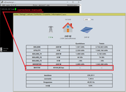
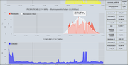
Grafico di oggi.

Re: Piranometro Arduino, qualcuno l'ha installato?
Ciao, interessante, c’è una spiegazione per cui il grafico della produzione non segue il grafico dell’illuminazione solare?
Io mi aspetterei di vedere una flessione dell’irraggiamento quando cala la produzione, così come il grafico dell’irragiamento me lo aspettavo più una sinusoide con la gobba abbastanza piatta piuttosto che un triangolo come nell’immagine.
Forse però mi sfugge qualche nozione di base.
Io mi aspetterei di vedere una flessione dell’irraggiamento quando cala la produzione, così come il grafico dell’irragiamento me lo aspettavo più una sinusoide con la gobba abbastanza piatta piuttosto che un triangolo come nell’immagine.
Forse però mi sfugge qualche nozione di base.
Sito personale: walter62.altervista.org
Re: Piranometro Arduino, qualcuno l'ha installato?
"E pue si muove", diceva Galileo Galilei.
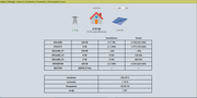
Battute a parte, la terra gira ed aggiungendo che la mia casa è di qualche grado orienteta a sud-est, il risultato è quello che vedi nell'immagine, Walter. Tieni conto che il grafico di cui sopra è schiacciato; infatti, nel grafico sotto, vedi che la curva è più piatta, avendo ristretto l'immagine ad un arco temporare più largo (se così si può dire).
Per quanto riguarda la curva della produzione è presto detto. Il mio impianto fotovoltaico non è connesso alla rete, percui la curva della produzione non si riferisce all'energia totale prodotta, ma soltanto alla quota parte di energia, che l'inverter preleva dai moduli, utile per alimentare i carichi + quella utilizzata per caricare e/o mantenere in carica le batterie + le inevitabili perdite. Purtroppo questo è uno dei limiti di questo tipo di impianto (l'altro sono le batterie).
Spero di essere stato chiaro nella spiegazione.
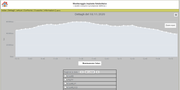
Chi c’è in linea
Visitano il forum: Nessuno e 13 ospiti